 |
Video_EXposure_Analyzer |
 |
|
Video_EXposure_Analyzer |
|
VEXA 1.0, developed from March to June 2006, is a tool to show the beginning and the end of the optical exposure within every single video field of a PAL or NTSC video camera or video modul. VEXA uses the extracted Vsync impulses from the analog video signal to synchronise a row of 10 switched LEDs to show the position and duration of the optical exposure window in the video fields. This tool was designed to test cameras with an exposure duration of a field or shorter. So VEXA can be also a useful device for people with video time inserter to determine the accuracy of timestamped video fields. To make measurements one has only to record the 10 LEDs of VEXA with the camera in test.
Copyright notes: Download and use of this informations and files is free, but on your own risk and only allowed for uncommercial use.
Copyrights are hold by the developer of VEXA and author of this site - Gerhard Dangl.
Link to newer version VEXA 2.0
Contents of this VEXA 1.0 page and some links
FAQ - Frequently Asked Questions
VEXA 1.0 functional description
VEXA 1.0 free download files - build your own VEXA
Images of a selfmade VEXA 1.0 prototype
Signal measurements on VEXA 1.0 prototype
VEXA measurements - CCIR video modul SK1004XC/SO
VEXA measurements - CCIR video camera WAT-120N
Geoff Hitchcox (New Zealand), the developer of Video time inserter KIWI-OSD,
used some VEXA measurements for A detailed look at KIWI OSD video timestamps.
Many thanks to Geoff Hitchcox and to Dave Gault (Australia) for assembling the first "external" VEXAs and performing very useful measurements. Additionally many thanks to Geoff Hitchcox for good ideas in VEXA circuit design.
In the meantime after VEXA was used in Austria, New Zealand and Australia it was also used in California by astronomers. Many thanks to all of them and especially for sharing the measurement results about their video camera.
|
1.) What does VEXA mean? VEXA is an abbreviation of Video_EXposure Analyzer. VEXA consists of free available hardware components and of by me programed software for functions control.
2.) What can be done with VEXA?
3.) Which cameras can be tested and measured with VEXA?
4.) Is it possible to test also video cameras in integration mode with VEXA?
5.) Is it possible to test also USB-cameras or Fire-Wire cameras?
6.) How are measurements taken with VEXA?
7.) Is it possible to make a direct check of Video Time Inserter (VTI) accuracy with VEXA?
8.) Can I order VEXA as a ready device or as a kit?
9.) How much are the costs of material for self-constructing a VEXA?
10.) Which power supply is needed for VEXA? |
VEXA functional description
Overview:
VEXA is using a row of 10 synchronised and switched LEDs to show the position and duration of the optical exposure window in the video fields. To measure exposure time one has only to record the 10 LEDs of VEXA with the camera in test. The ideal distance will depend on used camera-lenses. You should vary the brightness of the environment in the field of camera view to see how the camera change exposure time window.
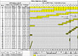
For exactly measurements 32 modes can be selected with a DIP-switch. Read the file from the download section about VEXA_Mode and Function carefully and you will grasp how to use differnt modes for exact measurements.
With a potentiometer the LED brightness can be adjusted over a wide range. CCD or CMOS cameras are able to record the glow of red Leds although they seem to appear dark to the human eye. So on the other side to much LED brightness will outshine the 10 single positions of lit LEDs.
VEXA needs a power supply in the range of 7 - 15 Volt DC and 30mA for working. You need a right AC/DC power supply adapter. With a new 9 volt battery an operation of 3 - 4 hours also should be possible. Connect the camera output with VEXA Video Input and to record or see exposure and regulation of exposure in realtime you have to connect VEXA Video Output to a monitor, a Videorecorder or a Videograbber useing a PC or Notebook for recording or monitoring.
VEXA is using the extracted Vsync impulses from the analog video signal to synchronise the internal starts of the LED row runs. After a start always only one single LED (01 - 10) after another is lit. The delay between Vsync and start of LED 01 and the time steps between the single lit LEDs are controlled by selected mode (00-31). VEXA can also distinguish the odd and even fields of PAL or NTSC video signals. So one can choose a LED row run only in odd, only in even or in both fields.
Example - idealised timing:
In our example we assume the exposure automatic of our camera exposures a duration of 12ms every field. The starting point is 8ms after the Vsync. The exposure window is lasting to the end of the video field at 20ms. If we would darken the field of view of our camera the automatic would start exposure window some milliseconds earlier than in our example.
What will we see in our example on a recorded PAL video sequence or on a monitor showing the live video of recorded LEDs? No exposure was done during lit of LED 01, 02, 03 and 04. So LED 01 to LED 04 are dark (0-8ms) and LED 05 to LED 10 (8ms - 20ms) are lit during exposure window and are shining bright in recorded video or on a monitor. We are able to determine the lasting (6 x 2ms = 12ms) and additionally the exact position of exposure in every video field. See the image below with idealised video timing for graphical description of this results.
Example - real timing:
How can we see such an offset time between the camera video field signal output (Vsync) and the internal exposure sequence using VEXA? A real value for this offset time is less than one millisecond. Lets take a look at the following image about real timing assuming an offset time of one millisecond. Remember, we are runing VEXA in Mode 00. So LED 01 is lit immediately after Vsync for 2 ms. Due to the offset at this time point the internal exposure window has not finished and is still going on for about another 1 ms.
What will we see on records or on a monitor showing the video of recorded LEDs? LED 01 in half brightness because it is captured only for 1 ms at the end of exposure field, no exposure was done during lit of LEDs 02, 03 and 04 so they look as complete dark, LED 05 is captured only for 1 ms at the start of exposure field and shine in half brightness like LED 01 does. Only the LEDs 06, 07, 08, 09 and 10 are captured each for 2ms and so are full lit. If we add all the lit times 1ms + 5 x 2ms + 1ms we get again the right exposure duration of 12ms.
Now we can use other VEXA-modes to determine this results with a higher resolution in time. The only thing we have to consider is, if LED 01 is lit also on short exposure times, an internal time offset between the camera video field signal output (Vsync) and the internal exposure field exists. And in this case LED 01 shows us the End of the exposure window and not the Start. The existing and the values of offset times are different and depends always on video camera or modul types.
Additional Note for use of NTSC cameras:
Now, after reading all this theoretical descriptions you should additionally take a look on the images of real Vexa-measurements accomplished with my CCIR video module SK1004XC/SO and video camera WAT-120N.
VEXA measurements - CCIR video modul SK1004XC/SO
VEXA measurements - CCIR video camera WAT-120N
Note: Download and use of this information and files is free, but on your own risk and only allowed for uncommercial use. Copyrights are hold by the author of this site. It is possible that files and their contents are modified from time to time.
Files for download (first prototype):
VEXA_Introduction in shortform (vexa.txt - 2kB)
VEXA_Mode and Function (vexa_mod.xls - 89kB)
VEXA_Schematic (vexa_sch.gif - 43kB)
VEXA_Bill of material (vexa_mat.xls - 18kB)
VEXA_Board (vexa_bd.gif - 32kB)
VEXA_Board_vias (vexa_via.gif - 50kB)
VEXA_Layout (vexa_pcb.gif - 49kB)
VEXA_Additional Pullups (vexa_add.gif - 2kB)
VEXA_Prototype_PCB (vexa_pc2.jpg - 74kB)
VEXA_Software V1.0 in Intel Hex format (vexa.hex - 5kB)
VEXA_Software V1.0 in Binary format (vexa.bin - 2kB)
All this VEXA - Download Files at once in zip-format (vexa_all.zip - 273kB)
This measurements of internal signals on a Vexa prototype are only for additional technical information. This images and the knowledge about are not needed for building and use of a Video EXposure Analyzer - VEXA.
VEXA is a simple microcontroller-circuit for showing and testing the exposure duration of a video camera or a video modul. VEXA is a tool to show the beginning and the end of optical exposure within every single video field. This tool was designed to test cameras with an exposure duration of a field or shorter. Modern cameras are able to vary exposure time-window from as long as all the field time (PAL=20.00000ms, NTSC=16.68335ms) to the shortest time in the range of only about 10 microseconds. The exposure window mostly starts at a variable timepoint in a field lasting to the end of the field. But some video modules are starting exposure time on a fixed timepoint and then variegate the exposure end in the field.
Video EXposure Analyzer - VEXA
(functional diagram)
We are using a PAL camera with 20ms video field duration and VEXA runing in Mode 00. Vexa waits on Vsync impuls and starts LED row immediately with LED 01. In Mode 00 every LED from 01 to 10 is lit one after another for exactly 2 ms. After 20ms all ten LEDs had lit each for 2 ms and now the next video field will start with the next Vsync impuls. The same cycle starts again and so on.
Note: The maximum exposure time in a single video field is nearly 20ms for a PAL video camera and would be nearly 16.68ms for a NTSC video camera.
Example video timing - idealised 
![]()
Live video image of all 10 Vexa-LEDs on a monitor
And now the same example as before but with real camera timing. The exposure duration is the same (12ms) as in our example before. But in reality there mostly is an offset time between the camera video field signal output (Vsync) and the internal exposure sequence. This little offset was detected by Geoff Hitchcox on some of my earlier measurements on video modul SK-1004XC using my KIWI-OSD with 1PPS LED and an oscilloscope. And this was the reason for me to start developing a device like VEXA to be able to measure the exact exposure behaviour of video cameras and video modules.
Example video timing - real 
![]()
Live video image of all 10 Vexa-LEDs on a monitor
A LED row run always ends at the latest on the next Vsync impulse or earlier after the 10 LED lit-times are over depending on the selected mode. The maximum selectable run time is Mode00 with 10 x 2ms = 20ms. This is the full time of a PAL field. But if you use a NTSC camera in this mode you will see that the LED run ends at LED 09 due to the next Vsync after 16.68335ms. So with signal from a NTSC camera LED 10 will never be lit in this mode.
Download Files for building your own VEXA
(wrongly absent on VEXA_Schematic - vexa_sch.gif)
with additional Pullups soldered over V13 and V14
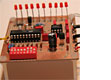
Images of selfmade VEXA (first prototype)
Selfmade VEXA - ready for use 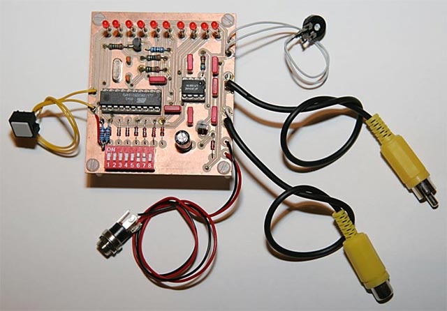
Details of LEDs 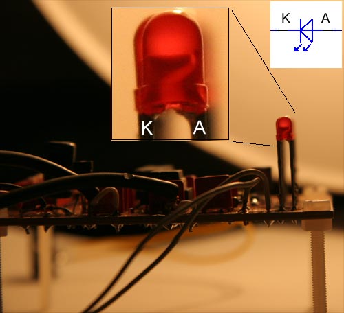
Details of the two extra pullups over V13 and V14 - top view 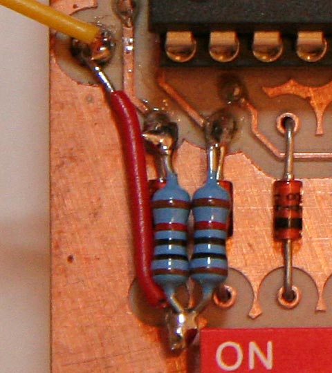
Details of the two extra pullups over V13 and V14 - side view 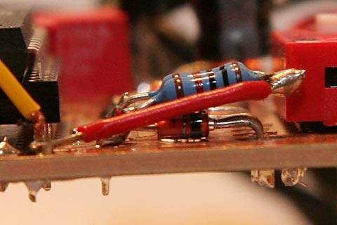
Details of the external 100k Pot used for LED brightness 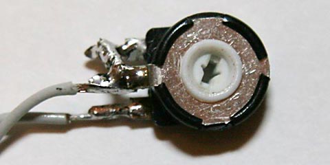
Signal measurements on VEXA prototype
Time delay Vsync and Even/Odd signal
Starting time of LED 01
Time delay between Even/Odd signal (Pin7) and Vsync (Pin3) of LM1881 |
The delay between Vsync and signal "Odd field start" is 2 us.
|
Light of LED 01 never starts earlier than 9us after Vsync |
LED 01 in Modes 00, 03, 08, 14, 21 and 31
|
February 23, 2008 |
|
Site Home |