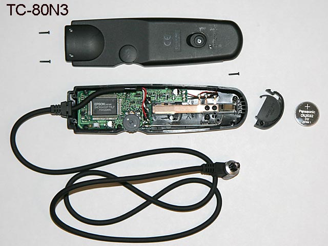
This page was made to show some important details of assembly and time switch behaviour of programable timer remote control Canon TC-80N3. To show the signals 3 volts were used. This voltage is certainly not present in real operation. Only timings of the signals should be shown here.
Note: I can not assume any liability for use of this page and for the results of this measurements.
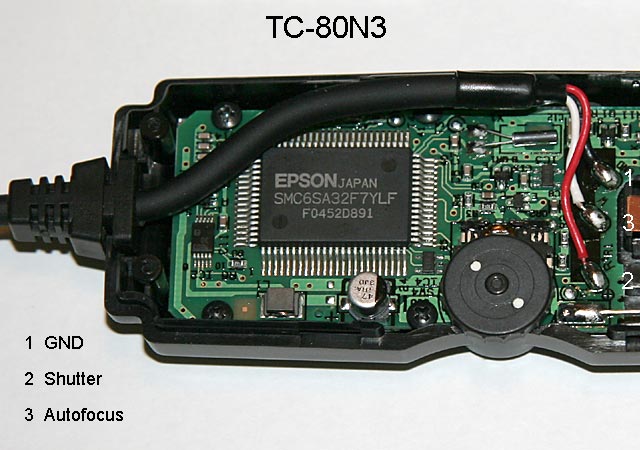
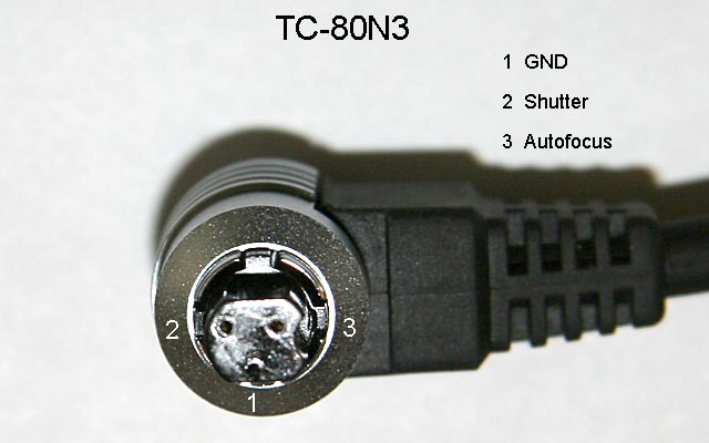
| TC-80N3 overview | Cable soldering points on TC-80N3 PCB | N3 plug detail |
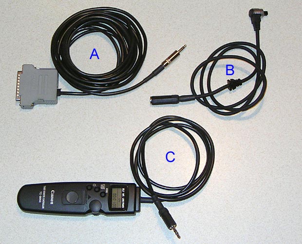
A: Selfmade new Parallelcable as described at the cablepage of Chris Venter.
B: Originalcable of TC-80N3 with new stereo jack - but uncutted and unshortened.
C: Programable timer remote control TC-80N3 with new longer cable and stereo plug.
Notes:
Take a look at the double activating of focussignal in diagrams 4, 5 and 6.
The diagrams 7 and 8 are showing clearly the delay of 240ms between focus signal and shutter signal.
| Diagram 1 | Channel 1 = Autofocus Channel 2 = Shutter Timebase = 10ms/Div Typical manually mechanical keypress with a delay of 35ms 
|
| Diagram 2 | Channel 1 = Autofocus Channel 2 = Shutter Timebase = 1s/Div Interval 5 seconds - exposure 1 second 
|
| Diagram 3 | Channel 1 = Autofocus Channel 2 = Shutter Timebase = 1s/Div Self timer with 5s delay time - exposure 1 second 
|
| Diagram 4 | Channel 1 = Autofocus Channel 2 = Shutter Timebase = 2s/Div Self timer with 10s delay time - exposure 1 second 
|
| Diagram 5 | Channel 1 = Autofocus Channel 2 = Shutter Timebase = 5s/Div Self timer with 25s delay time - exposure 1 second 
|
| Diagram 6 | Channel 1 = Autofocus Channel 2 = Shutter Timebase = 5s/Div Self timer with 40s delay time - exposure 1 second 
|
| Diagram 7 | Channel 1 = Autofocus Channel 2 = Shutter Timebase = 0.2s/Div Exposure with duration of 1s - electronically release with Start/Stop button 
|
| Diagram 8 | Channel 1 = Autofocus Channel 2 = Shutter Timebase = 0.5s/Div Exposure with duration of 2s - electronically release with Start/Stop button 
|
| Diagram 9 | Channel 1 = Autofocus Channel 2 = Shutter Timebase = 5s/Div Exposure with duration of 40s - electronically release with Start/Stop button 
|
02. May 2006 |
|
Site Home |