Precision time measurement with GPS and PC
| Frameless version of this page |
During visual observation or video-recording of astronomical events, one needs in addition very accurate time recording. Accuracy of approximately 1/20 second is enough for visual observations, the requirement rises with video time insertion into the range of 1/1000 seconds.
During video-recording into each PAL half-image the milliseconds exact time is added. So each picture in the PAL system can be assigned to a specific time with a tolerance of +/- 10 ms. A solution from Geoff Hitchcox from Christchurch in New Zealand with a circuit for video with accurate time recording is the KIWI OSD.
| Kiwi-OSD System - built October 2005 |
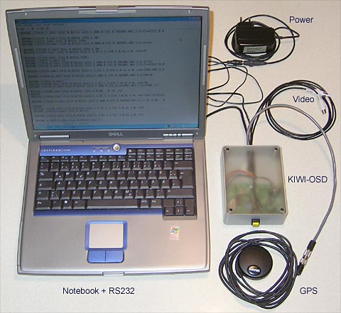 Notebook, GPS Garmin 18 LVC and KIWI-OSD |
Visual observation
During a visual recording observation, a switch can be pressed at the instant of an event. Thus the event is provided with a time stamp and can be analyzed later.
One knows the exact time by a relatively simple means with GPS. Against this method the radio clock system DCF-77 appears relatively inaccurate. With the DCF-77 receive deviations can result in up to several milliseconds from amplitude oscillations and different distances from the transmitter. With a suitable GPS sensor, which supplies an exact PPS signal, one can reach however accuracies within the range of only a 1/10000 second.
Geoff Hitchcox from New Zealand developed a simple circuit suggestion and also the outstanding DOS Freeware KIWI Precision time Stamp utility.
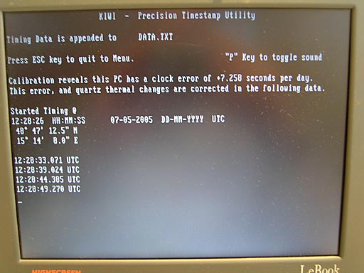
The KIWI Precision time Stamp utility is optimal for visual observations with exact time recordings. Each keypress is written with exact UTC into a file and is thus later callable.
Here is the description of my following reproductions
| Notebook screen |
 |
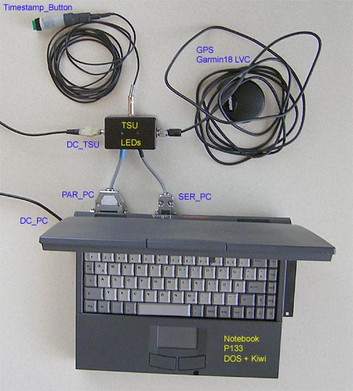
The picture below shows the interconnection of all necessary components in my reproduction. The small box TSU contains the simple circuit with the few construction units as well as the necessary wiring. The GPS sensor I use is the type GPS18 LVC. This modern 12-channel with integrated SBAS (Satellite Based Augmentation Systems) correction and 1PPS has a horizontal position accuracy better than three meters. The SBA-System EGNOS (European Geostationary Navigation Overlay Service) is announced to become operational for non security applications for the first time about the middle of 2005. In 2006 EGNOS should become operational for all applications. In addition to a temperature range from -30°C to +80°C, the sensor has a waterproof housing and integrated detention magnet. From the Internet site of the company, a free Software tool can be downloaded for configuring the sensor. With the application KIWI - only the two NMEA0183 strings $GPGGA and $GPRMC and the 1PPS signal are required from the sensor.
| Interconnection of the components |
 |
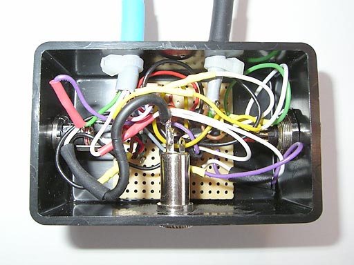
A first prototype circuit was developed by me on a hole raster plate and built with patch cords into a small plastic housing. As usual is the case for prototypes, an arranged wire-rod guide was no longer possible after several around and annexes. Therefore on the inside now a functioning chaos prevails ;-).
| TSU - prototype plate and wiring |
 |
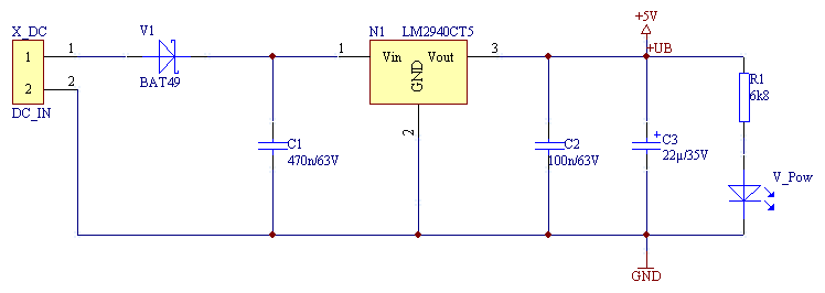
I extended the circuit suggestion of Geoff Hitchcox with my circuit with a safe voltage supply. Thus input voltages are possible in a wide range from 4,5 to 15 V. The circuit has also a power LED and is additionally protected from wrong polarity.
| TSU circuit - voltage supply (4,5V - 15V DC) |
 |
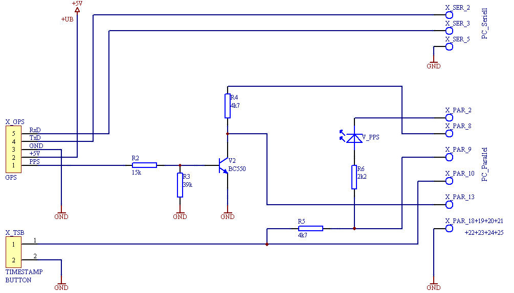
This second circuit corresponds mainly to the suggestion of Geoff Hitchcox. Here all components are connected accordingly. The transistor inverts the rising 1PPS signal of the GPS18 LVC at the beginning of the second, to a falling transition. The KIWI software requires a falling transition. When using another GPS sensor with falling pulse on the 1PPS, one does not need this inverting transistor V2 and resistances R2, R3 and R4 naturally.
| TSU circuit - signals and connections |
 |
This measurement shows the two data strings and the 1PPS signal. One sees already here that the 1PPS signal is sent slightly before the two data strings.
| Channel_1: TxD (NMEA0183 $GPRMC + $GPGGA) Channel_2: 1PPS |
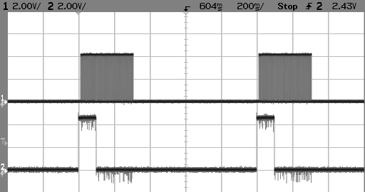 |
In this measurement a time misalignment of 14ms between 1PPS signal and data string becomes evident. This time misalignment is not however by any means constant and varies, dependent on the GPS receive situation, varying within the range of approximately 10 - 20 ms. With the GPS receiver the cost of computation in the GPS module varies and thus also this time misalignment changes.
| Channel_1: TxD (NMEA0183 $GPRMC + $GPGGA) Channel_2: 1PPS |
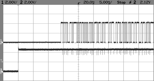 |
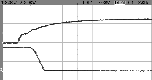
The three meter long connecting cable of the GPS18 LVC sensor was extended by seven meters to 10 meters. Shown in this measurement, a safe level change of the 1PPS is done in 200ns. Therefore one can still operate the sensor without problems with such conduit lengths. The signal is delayed additionally by the inverting transistor around 150ns. So in this circuit the 1PPS will be delayed by approximately 350ns. Together with indicated basic accuracy of the 1PPS signal of +/- 1 microsecond is however still reached a much better accuracy as a 1/10000 second.
| Channel_1: 1PPS signal direct from Garmin GPS18 LVC |
| Channel_2: 1PPS signal to PC after transistor inverter |
 |
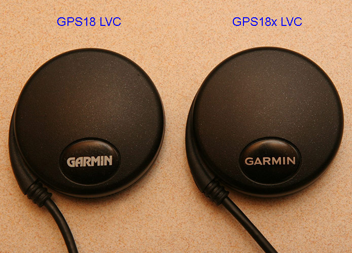
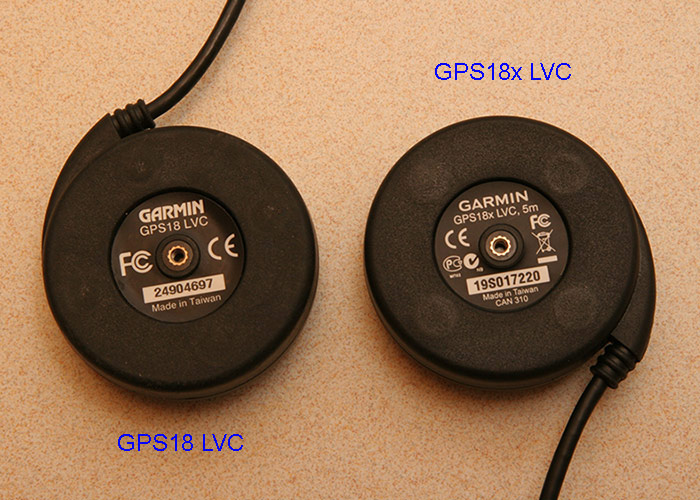
Next page - The GPS sensors GPS18 LVC and GPS18x LVC in comparison
 |  |
March 15, 2009 |
|
Site Home |