EXposure Time Analyzer - EXTA
| Frameless version of this page |
Pages of the EXTA project
Page #1 - Main page with EXTA description (this page)
Page #2 - Measurements with analog video camera modul SK1004XC
Page #3 - Measurements with analog video camera WAT-902H2 Ultimate
Page #4 - Measurements with integrating analog video camera WAT-120N
Page #5 - Measurements with Astro CCD camera Atik 314L+
Page #6 - Measurements with IOTA-VTI device
Page #7 - Measurements with integrating analog video camera MINTRON 12V1C-EX
Temporary note:
This pages about the EXTA project are not completed at the moment, some may be edited again and some additional pages may be published during next weeks. So please make a revisit to read the updated pages in a final bilingual (English and German) version and with all the measurements here.
EXposure Time Analyzer - EXTA
The development of this device started in 2010 and could be finished in 2011. The primary goal for this development was a device to determine the optical exposure time window of a camera system in absolut UTC format over a wide exposure time range and with a resolution in time down to one millisecond. But beside cameras this device can also measure the accuracy of Video Time Inserters - VTI. Because of the relative complex design required for this functions and the big display with a large number of LEDs the goal was not to develop this device for reproduction. So at the moment it will stay as a very useful prototype device. The advantage of EXTA is the big LED matrix with 1000 LEDs. Because of this high number of LEDs and the different modes also exposures with longer durations can be measured with a relative high resolution in time. In the best case a UTC time accuracy of 1/1000 of the total exposure length can be evaluated. Typical applications will be the timing measurement of several camera systems and Video Time Inserters used in astronomy.
EXTA prototype device - front view with LED matrix displays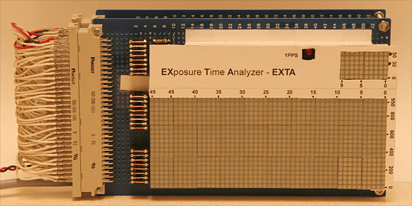
EXTA prototype device - top view with Microcontrollers inside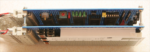
EXTA prototype device - backside wiring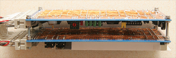
Camera systems which can be measured
With EXTA the error of software controlled camera systems based on synchronized PC clocks can be determined. This camera systems are the most common used by amateur astronomers for position determination of an object in space with a resolution in time down to one second and in some special cases down to tenths of a second. For data recording of fast moving objects or for short events a higher resolution in time is needed. Therefor mostly analog video based camera systems with additional video time inserter (VTI) are used. In this systems the internal timing behaviour of the video camera can be determined with EXTA too. Particularly the internal timing behaviour of an integrating video camera can be sometimes a difficult and time intensive "mystery" to solve without a device like EXTA. High image speed digital signal cameras with USB or Firewire interface can not be used with a hardware time inserter like analog video cameras. Here other solutions are used for exposure time determination. Some of them are software based. The time accuracy of any of this methodes can also be measured with EXTA. And to measure the real exposure length of a digital image camera, a mobil phone cam or a DSLR is also an easy task. So in short the exposure of nearly every camera system can be checked or measured with EXTA down to split seconds of 1/1000s.
Video Time Inserter - VTI which can be measured
With EXTA the accuracy of the UTC time insertion by any VTI can be measured too. Because not every VTI for analog video is time stamping the fields of the signal in the same way it is very important to know about the timing behaviour of the used device. The time differences are mostly in the range of one video field. Not a big error in events lasting for many seconds. But in very short events this can became a relevant error. So every user has to know about the details to be able to correct times before reporting.
Location and environment of a measurement place
For measurements one has to power on the EXTA system (GPS+device) and place the GPS sensor direct on a window inside a building or somewhere outside for sufficient GPS signal reception. The EXTA device with the LED matrix display area should be placed so that it can be recorded by the camera system in test. Of course therefor the camera has to be mounted on a lens or an optic system for recording the EXTA display area (135x80mm) at once, in a nearly right angle and in focus. The light of the environment should be dimmed to get a good contrast of the lit LEDs. But the dark LEDs of the EXTA display should stay visible too. This is necessary because after the exposure we have to count all the lit and unlit LEDs in a recorded image for a sure evaluation. It also has to be mentioned that the environment light must be changed with the change of exposure duration to get always well defined lit and dark LEDs.
Basic function of EXTA
After power on the EXposure Time Analyzer device EXTA first waits with all LEDs on matrix display switched to dark until a valid GPS fix is accomplished. Depending on the local receiving situation this can last from less than one minute up to several minutes. After a GPS position fix the LED UTC second matrix (0 - 59) immediately and ongoing shows the current UTC second. And the fractions LED display starts a run with LED step times selected by the mode switch. Additional the 1PPS LED makes a flash at the begin of every UTC second with the duration set in the GPS sensor configuration.
The LED matrix display for the UTC seconds (6x10) is updated with every 1PPS output puls from the GPS. The LED fraction matrix display (0 - 999) runs with time step velocity determined by the mode switch setting until the LED matrix end is reached. A new start of the LED fraction matrix display is always triggered by the next 1PPS puls output from the GPS. In this way every new start of the LED fraction matrix display (20x50) run is synchronized also with a start of a UTC second.
If the GPS fix gets lost the LED matrix updates will stop until the GPS fix is accomplished again. But with the sensitive GPS 18x LVC sensor the GPS Sat signals must be very worse to get no fix after power on or to lost a fix during testing work. However, if this happens one should change an obviously very bad GPS sensor position to a better one.
EXTA function overview
Technical data
Power                       : 12V DC/200mA, EXTA has male connector 2.1/5.5mm with center pin plus
Reset                       : Power ON and manually with button
UTC time base               : Garmin GPS 18x LVC with NMEA0183 and 1PPS output
1 PPS UTC accuracy          : rising puls edge within 1µs until 4s after last fix
1 PPS puls length           : 20ms set in the GPS sensor by Garmin configure software
CPU unit                    : 5 Microcontrollers for functions and LED matrix displays
Time display                : UTC seconds and fractions of a second (dependent on mode)
LED fraction display        : 1000 LEDs matrix 20x50
LED UTC seconds display     :   60 LEDs matrix  6x10
LED display type            : Matrix 5x7, TC07-11SRWA Super bright red (GaAlAs)
LED wavelength peak         : 660nm (typ. 24mcd @10mA)
LED spectral line halfwidth :  20nm
LED UTC offset error        : smaller than 70µs (Software controlled)
Modes                       : Six (0-5) selectable with mode switch
Mode 0                      : Fraction LED step  1ms (total cycle time  1s)
Mode 1			    : Fraction LED step  2ms (total cycle time  2s)
Mode 2			    : Fraction LED step  5ms (total cycle time  5s)
Mode 3			    : Fraction LED step 10ms (total cycle time 10s)
Mode 4			    : Fraction LED step 20ms (total cycle time 20s)
Mode 5			    : Fraction LED step 50ms (total cycle time 50s)
LED relativ radiant intensity
LED matrix displays in detail
The small matrix with 6x10 LEDs shows the current UTC second from 0 to 59. The big matrix with 20x50 LEDs always starts synchronized with a UTC second start. Every LED (0-999) in this matrix is lit only for a fraction of a second. This fraction of a second is dependent on the mode chosen by the mode switch. So the time for a total run through from LED 0 to LED 999 can last from one second to 50 seconds. After the last LED lit time has ended the run through starts again but again triggered by the start of a new UTC second.
So with both matrix displays visible on a recorded image it is an easy task to determine which UTC time corresponds to every lit LED on the matrix displays. In this way the exposure start and end times are visble as absolute UTC on the recorded images. Althought all the LED matrix modules were purchased at once and from one distributor some LEDs of them have obviously different light flux if operated with the same current. This can became visible in the measurement images with short exposure times if the LED light does not saturate the CCD pixel. But it does not really affect the results and it is primary only a non-uniform look in the captured images. And in longer exposured images with CCD pixel saturation all the lit LEDs are shining in the same brightness.
There are two basic conditions to get useful measurement results
- The recorded image must show clear all the lit and the unlit LEDs on both matrix.
- The chosen mode has to guarantee that one run through of the big LED matrix lasts longer than the image exposure time of the camera.
Practical measurement range
Because the shortest LED step time in the big LED matrix is one millisecond every longer lasting exposure time will be sure visible. May be an exposure time below 1ms would be noticeable too as a non full lit LED. But such times are not resolved by several LEDs. So the shortest practical value will be one millisecond. The longest time measureable is limited by the slowest LED step. We have to take in account that the first and the last lit matrix LED in an image could be lit only partially and one LED between start and end should be surely dark. So with the longest 50 milliseconds LED steps we can measure exposures up to 49.850 seconds.
Exposure duration measurement range
≥ 00.001 s
≤ 49.850 s
Typical measurement setup
Camera with lens mounted is imaging the display area of EXTA
More details of the setup are shown in the individual measurement pages.
Pages of the EXTA project
Page #1 - Main page with EXTA description (this page)
Page #2 - Measurements with analog video camera modul SK1004XC
Page #3 - Measurements with analog video camera WAT-902H2 Ultimate
Page #4 - Measurements with integrating analog video camera WAT-120N
Page #5 - Measurements with Astro CCD camera Atik 314L+
Page #6 - Measurements with IOTA-VTI device
Page #7 - Measurements with integrating analog video camera MINTRON 12V1C-EX
October 10, 2012 |
|
Site Home |