Page #1 - History, decision and purchase of the Skywatcher EQ8 mount
Page #2 - Mobile setup of the EQ8 mount with Newton telescope
Page #3 - Current draw and power supply of the EQ8 mount
Page #4 - Detailed images of the EQ8 mount (this page)
Images from the area of the declination axis of the EQ8
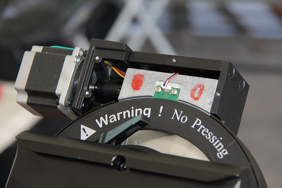
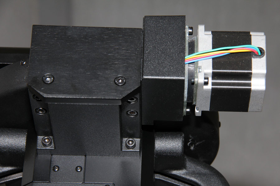
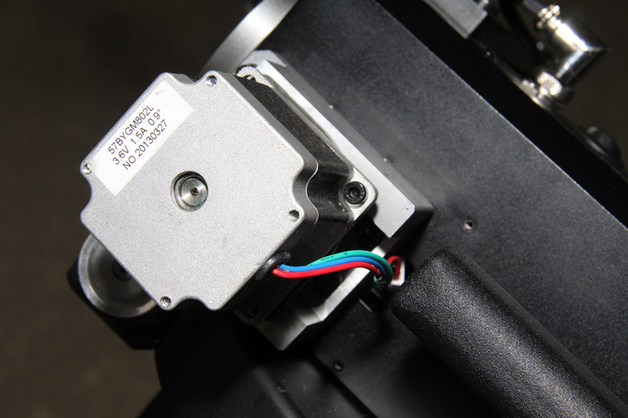
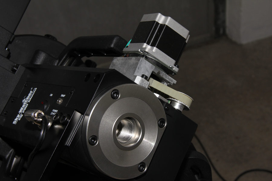
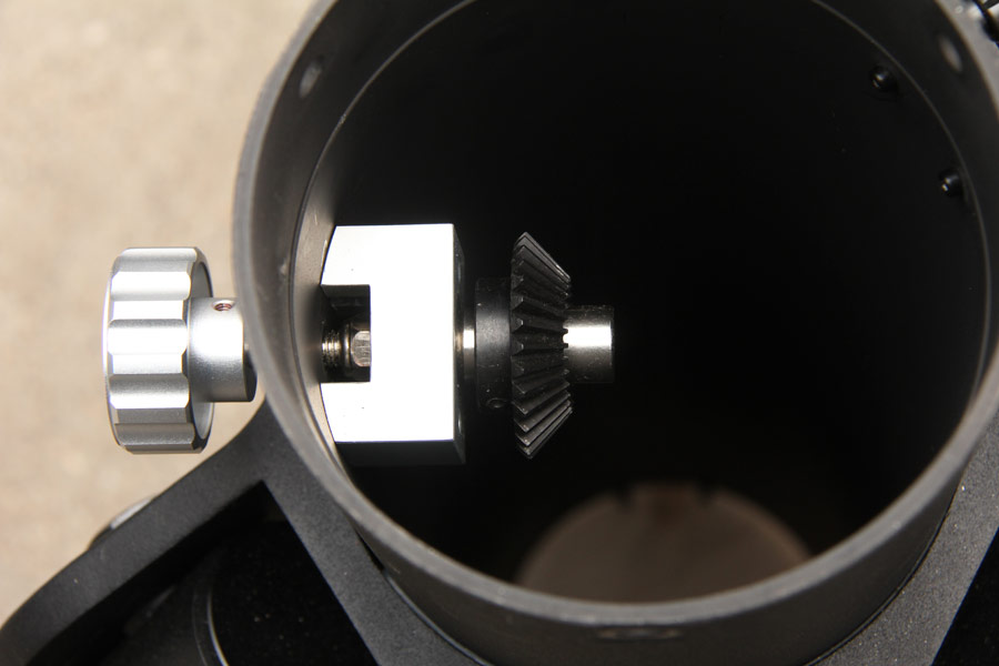
The stepper motor for declination axis driving is direct coupled to the worm gear. |
| |
| |
| |
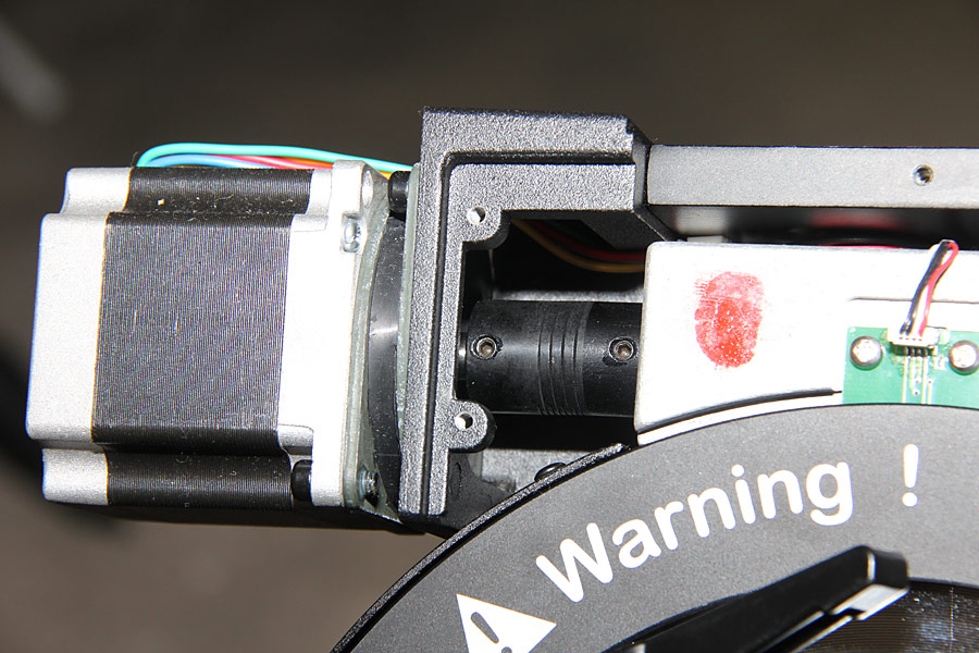
A flexible shaft coupling ensures the compensation of small alignment tolerances. The rubber mounting of the stepper motor is clearly visible. |
| |
| |
| |
The stepper motor for the declination axis has a full step resolution of 0.9 degrees. This corresponds to 400 full steps per revolution of the motor shaft. The control electronics ensures 50.625 arcseconds resolution with 64 micro steps per full step. This is enhanced by the 435:1 ratio of worm gearbox to 0.12 arcseconds. Overall, a turn of the declination axis can be achieved by 11136000 single movements of stepper motor shaft. The right ascension axis drive has the same gear reduction.
|
| |
| |
| |
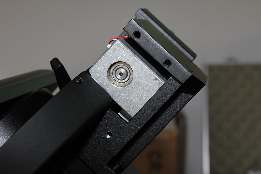
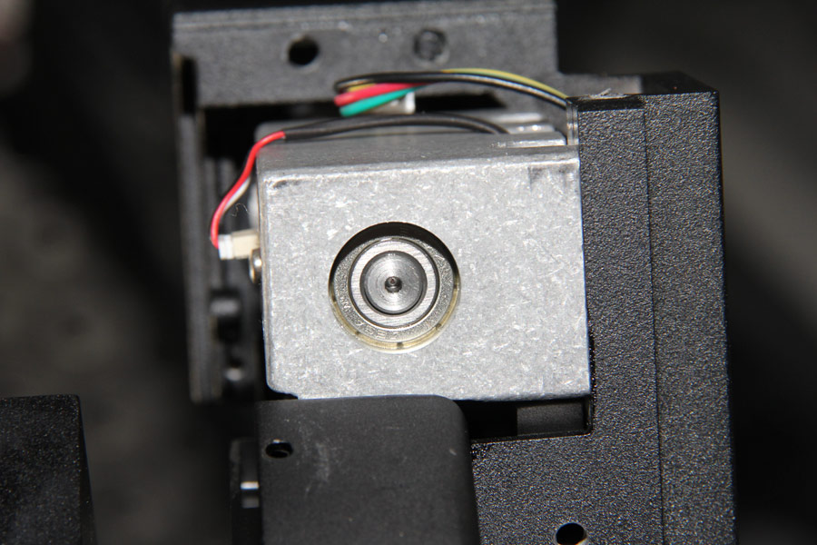
The ball-bearing of the declination axis worm. |
| |
| |
| |
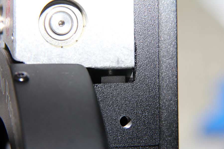
One adjusting screw for the declination worm backlash is visible below the Alu block here. |
| |
| |
| |
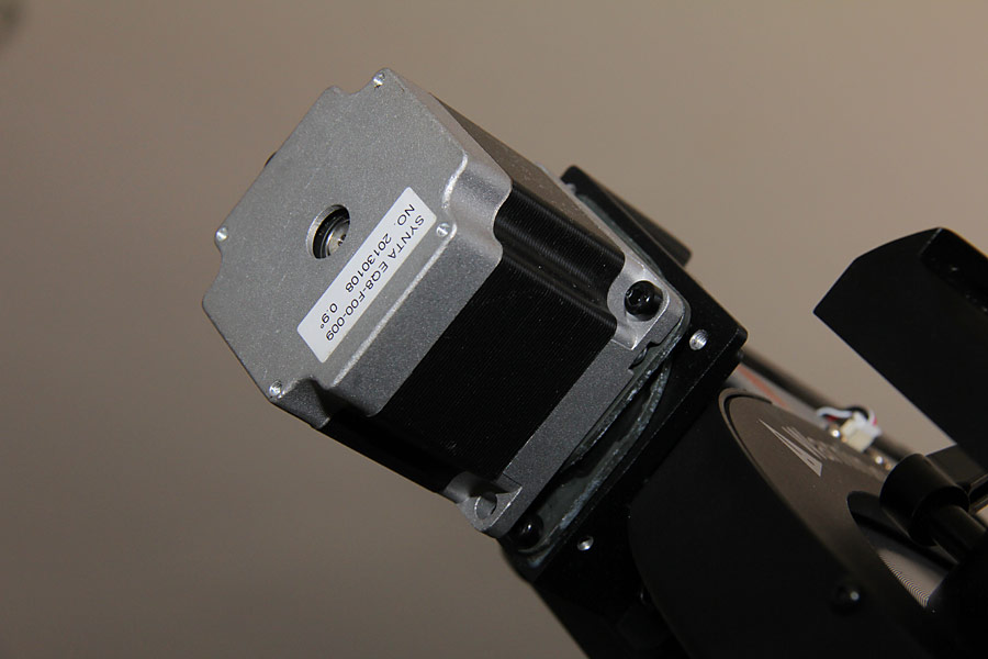
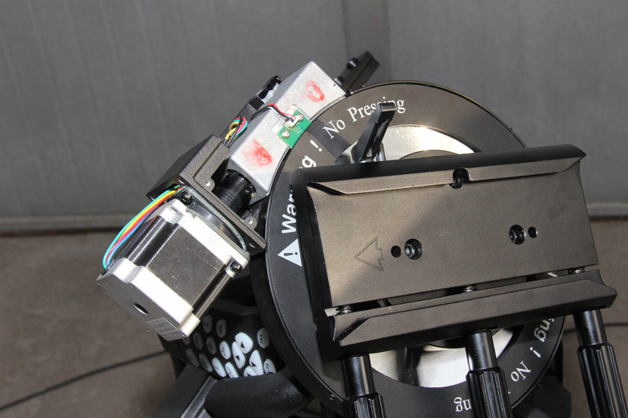
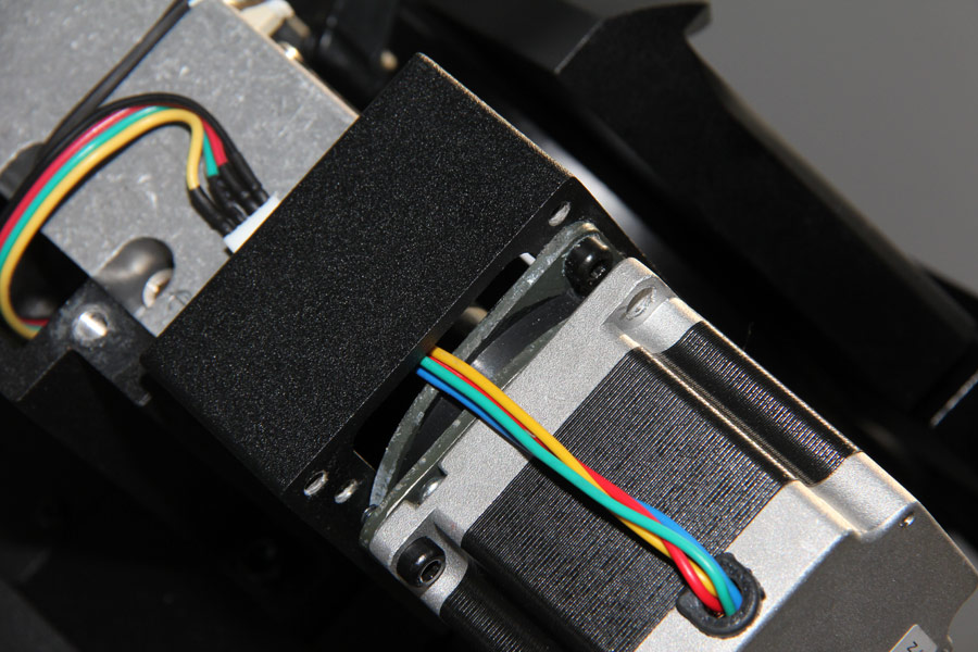
The stepper motor of the declination axis with unscrewed plastic cover. |
| |
| |
| |
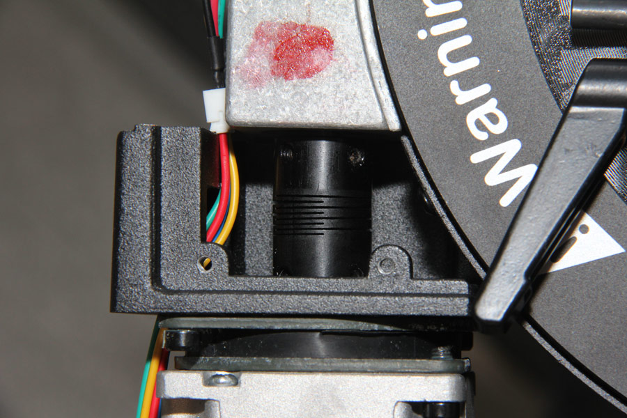
The rubber mounting of the motor and the flexible shaft coupling of the declination axis in detail. |
| |
| |
| |
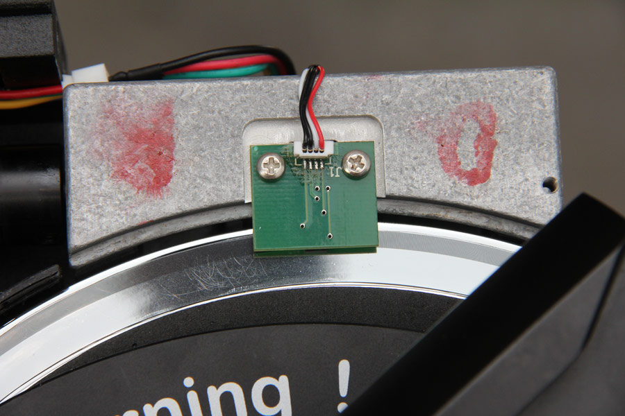
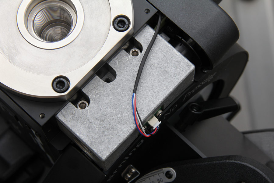
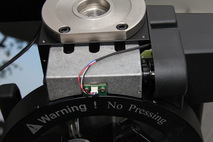
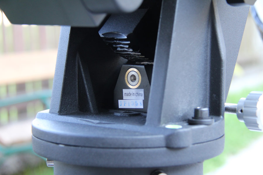
The reflecting light barrier of the encoder of the declination axis with removed protection cover. |
| |
| |
| |
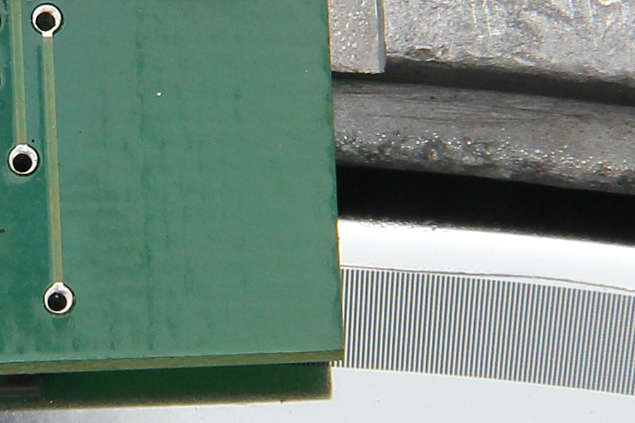
The bar code of the encoder is printed direct on the declination wheel and provides a resolution of 17624 positions per revolution. This corresponds to 1.226 arc minutes. On the right ascension axis an identically constructed encoder system is used. |
| |
| |
| |
Here the protection cover of the encoder of the declination axis is screwed on again. |
| |
| |
| |
The Alu bloc with a bearing of the declination worm. |
| |
| |
| |
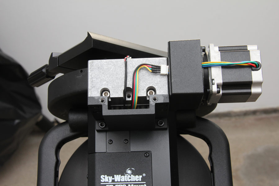
With the cover plate unscrewed all three adjustment screws for the setting of the worm backlash of the declination axis are visible. |
| |
| |
| |
The stepper motor of the declination axis with cable routing. |
| |
| |
| |
Images from the area of the right ascension axis of the EQ8
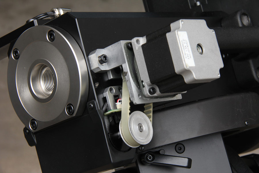
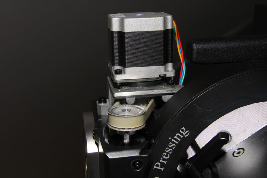
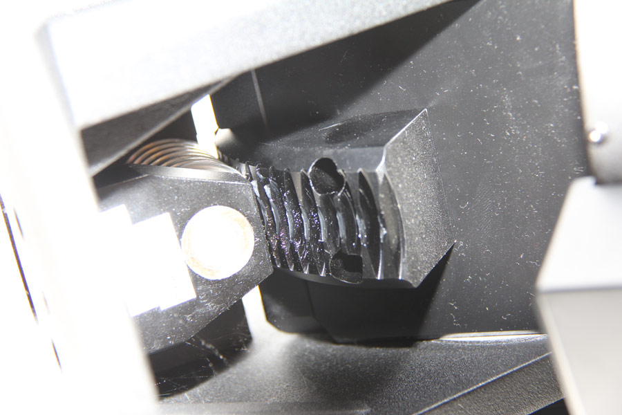
The picture shows the right ascension axis drive with unscrewed plastic cover. It is also driven by a stepper motor. In difference to the declination axis it is not coupled direct to the worm gear. A belt gear with a gear ratio of 1:1: is located here between the motor and worm. Because of this belt the motor could be mounted side offset. And it is possible to drive the right ascending axis nearly silently. |
| |
| |
| |
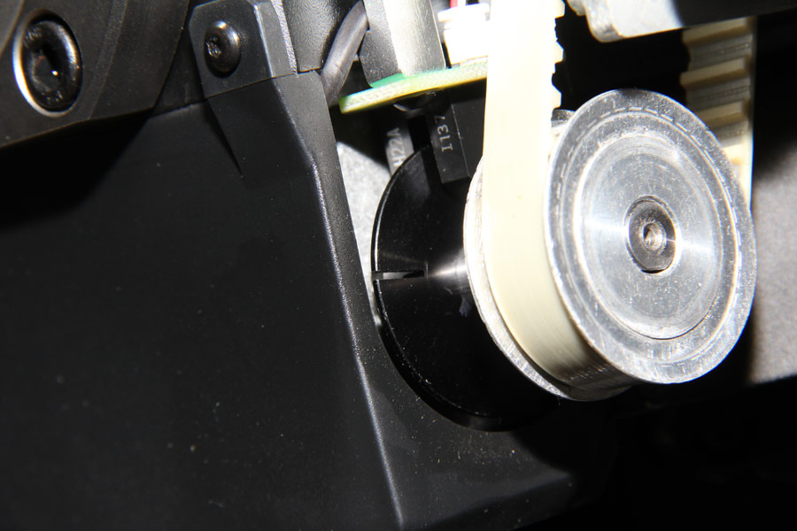
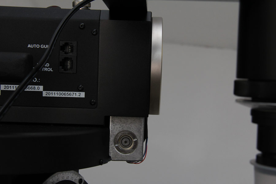
Direct on the drive shaft of the right ascension worm a fork light barrier is mounted to monitor the rotation. |
| |
| |
| |
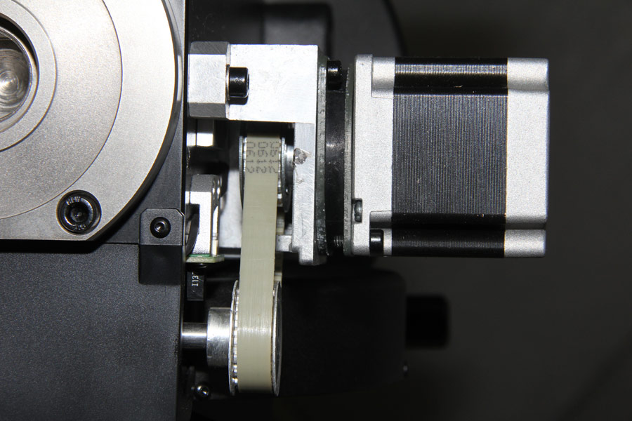
Also the stepper motor of the right ascension axis is screwed with a rubber bloc. The belt Auch der Schrittmotor der Rekatszensionsachse ist mit einem Gummiblock verschraubt. The belt compensates slight assembly tolerances. |
| |
| |
| |
The stepper motor for the right ascension axis has a full step resolution of 0.9 degrees. This corresponds to 400 full steps per revolution of the motor shaft. The control electronics ensures 50.625 arcseconds resolution with 64 micro steps per full step. This is enhanced by the 435:1 ratio of worm gearbox to 0.12 arcseconds. Overall, a turn of the right ascension axis can be achieved by 11136000 single movements of stepper motor shaft. The declination axis drive has the same gear reduction. |
| |
| |
| |
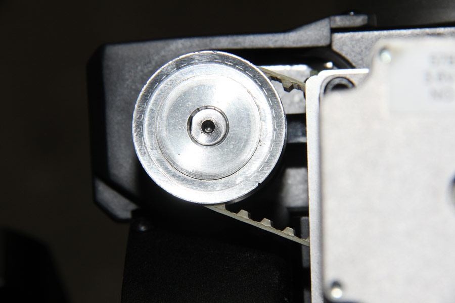
The toothed belt wheel of the right ascension worm shaft in detail. |
| |
| |
| |
On the worm wheel of the right ascension axis also a bar code for the encoder system exists. |
| |
| |
| |
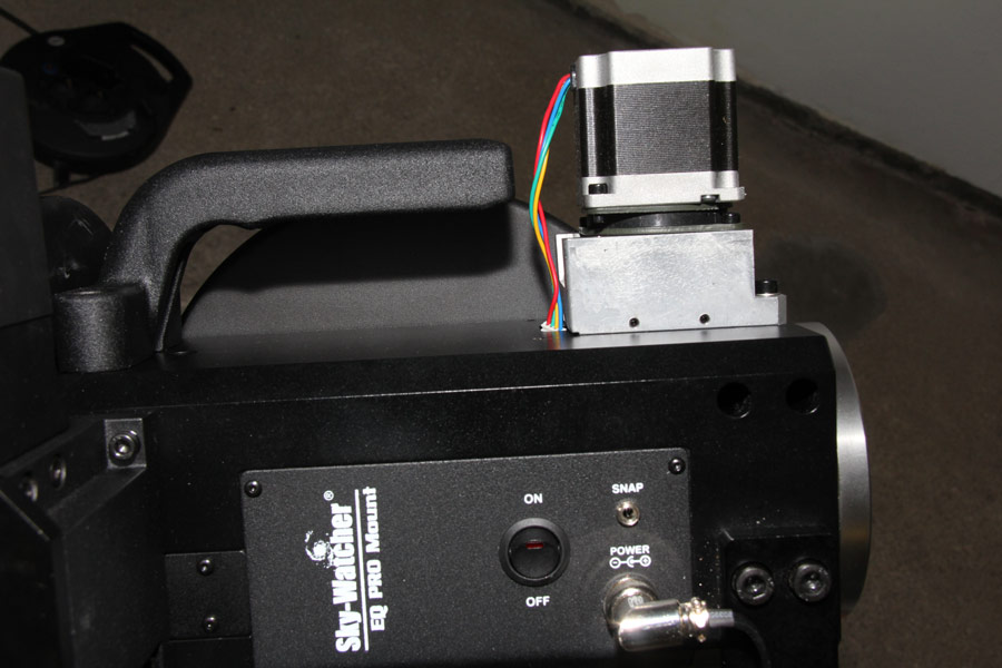
The motor of the right ascension axis with unscrewed plastic cover. |
| |
| |
| |
The solid inside thread to bolt the 40cm long counterweight bar. In contrast to the EQ6 the counterweight bar is not rotating with the declination axis on the EQ8. |
| |
| |
| |
Also the bearing bloc of the right ascension worm can be adjusted with three screws. |
| |
| |
| |
The reflection light barrier for the encoder system of the right ascension axis. |
| |
| |
| |
Ball bearing in the Alu bloc of the right ascension worm. |
| |
| |
| |
Images from the mount head of the EQ8
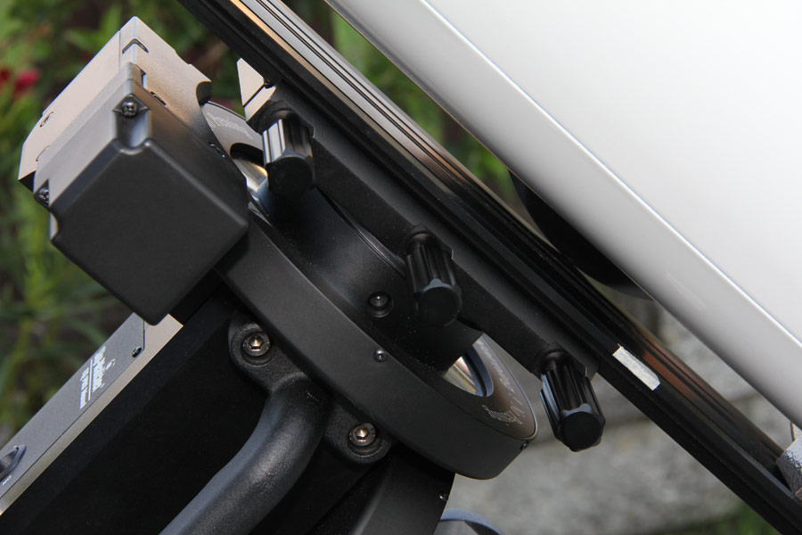
The mounting plate on the mount head is constructed for racks on the 3-inch Losmandy base. With the three srewing points also heavy optics up to the maximum load of 50kg can be clamped sure. |
| |
| |
| |
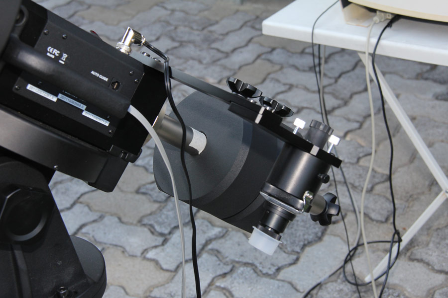
Only a power supply and a control cable are the necessary cables on the EQ8. |
| |
| |
| |
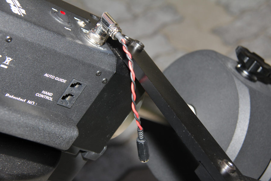
The power supply cable was modificated to work with the switching power supply. The angle socket is permanently screwd on the plug in the case. |
| |
| |
| |
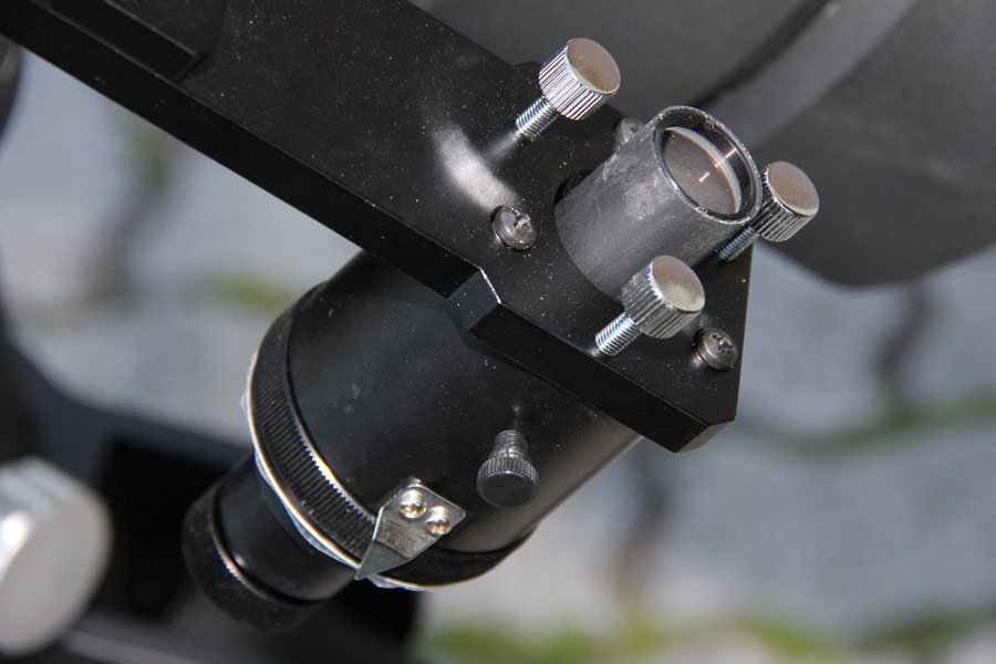
The pole finder can be adjusted good and provids a bright image. With it the alignment of the hour axis of the mount is relative easy. The achievable accuracy is sufficient for short exposure times. And with guiding also long time exposures are possible without problems. |
| |
| |
| |
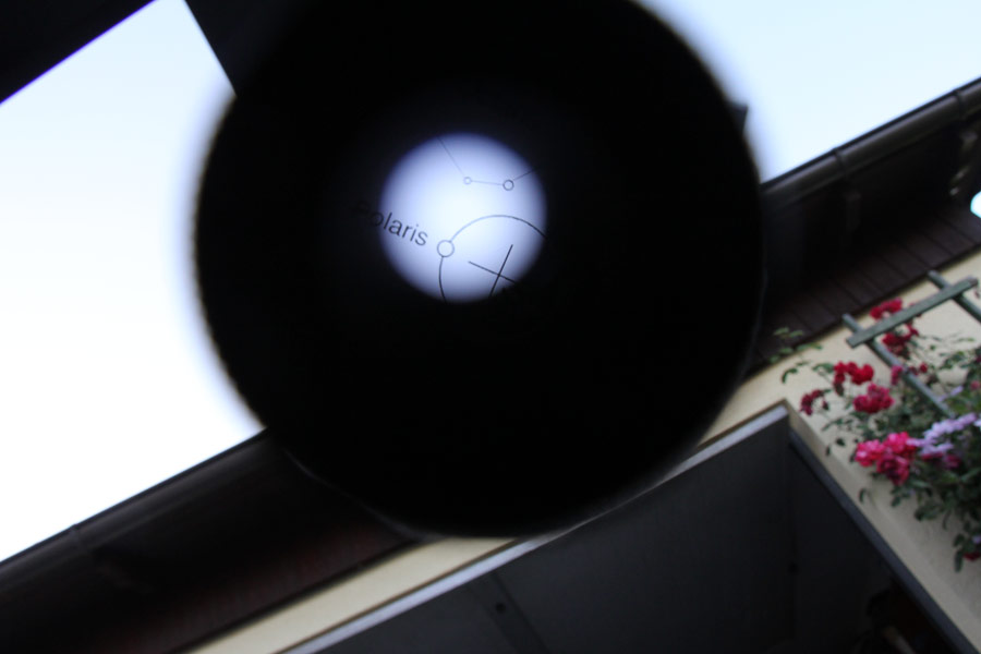
During the insight in the pole finder all EQ6 owner will see a familiar view. |
| |
| |
| |
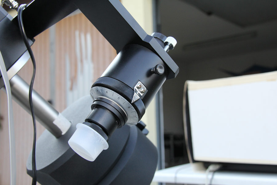
The coverages for the pole finder lens were not included in delivery. |
| |
| |
| |
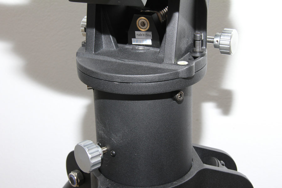
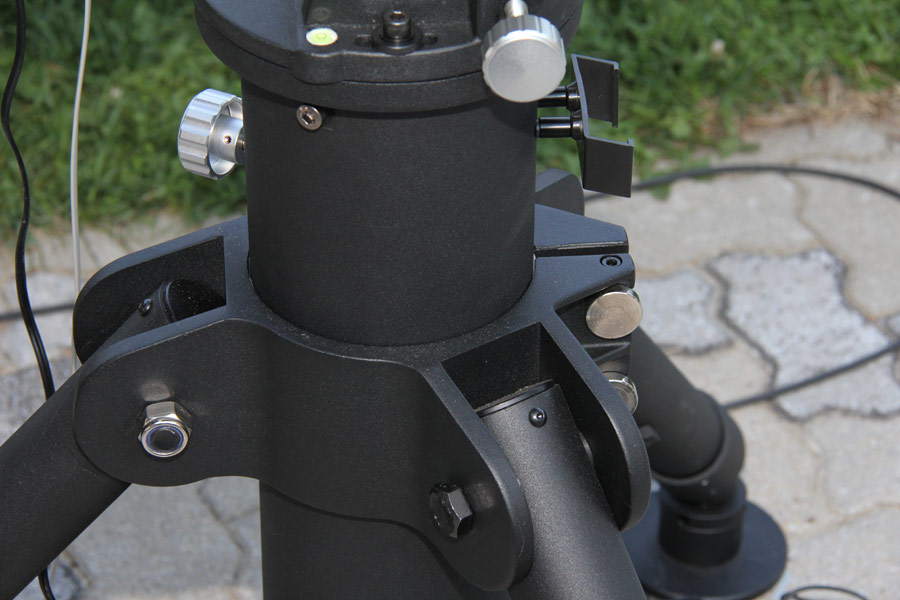
The mount head is fixed on the tripod with a central M12 screw and two M8 screws sideways. The big knurled knobs of the azimuth adjustment allow a fine adjustment of the mount head. |
| |
| |
| |
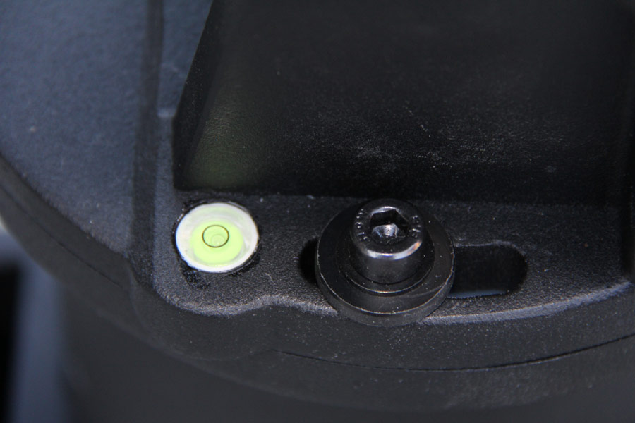
The mount haed has a simple level integrated in the base plate. Beside there is one of the two M8 fixing screws. |
| |
| |
| |
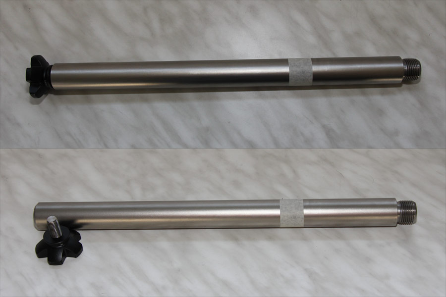
The solid counterweight Rod has a length of 40 cm and a diameter of 31.4 mm. It can quite hold up to 4x10kg counterweights. The locking screw at the bottom of the counterweight rod is also made very solid. A mark with a tape on the rod allows a correct and quickly positioning of the counterweights. |
| |
| |
| |
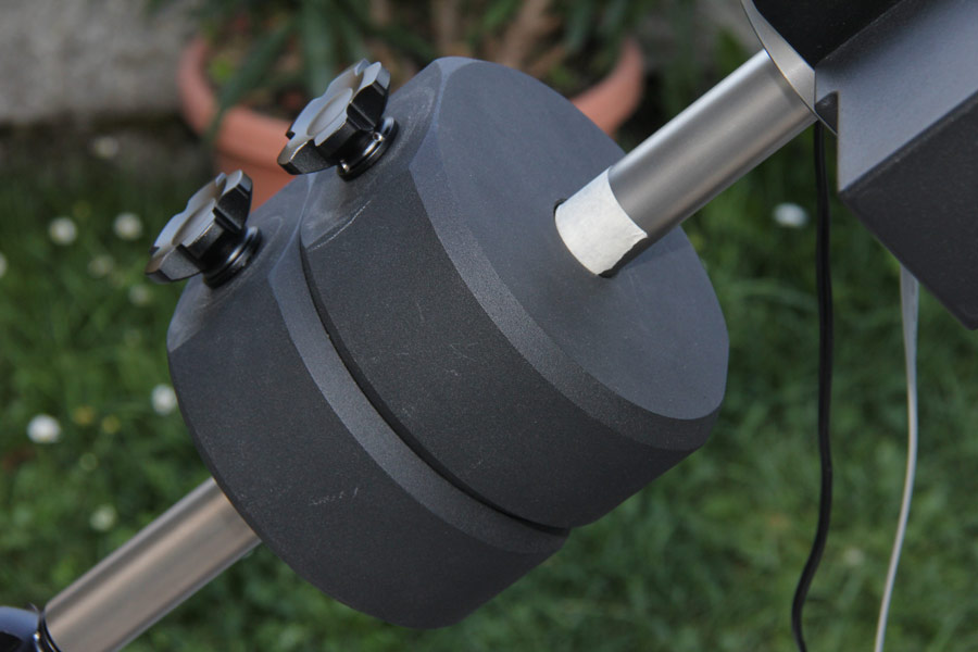
The counterweights with 10kg each are screwed on the marked position. |
| |
| |
| |
The adjustment of the pole axis altitude is made with a solid worm gear. Even under full load this is possible in a very easy motion. |
| |
| |
| |
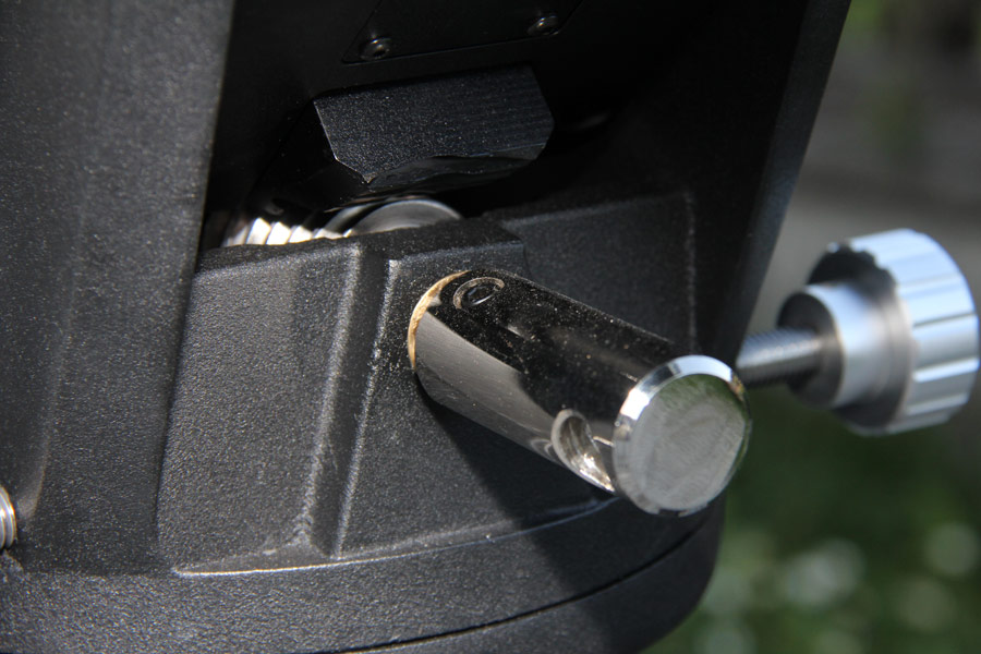
The worm gear for adjustment of the pole axis altitude is rotated with a connecting rod. This rod was removed here. |
| |
| |
| |
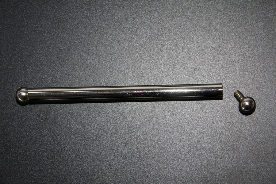
The connecting rod for adjustment of the pole axis altitude can be removed from the mount head. |
| |
| |
| |
The worm gear for adjustment of the pole axis altitude inside in detail. |
| |
| |
| |
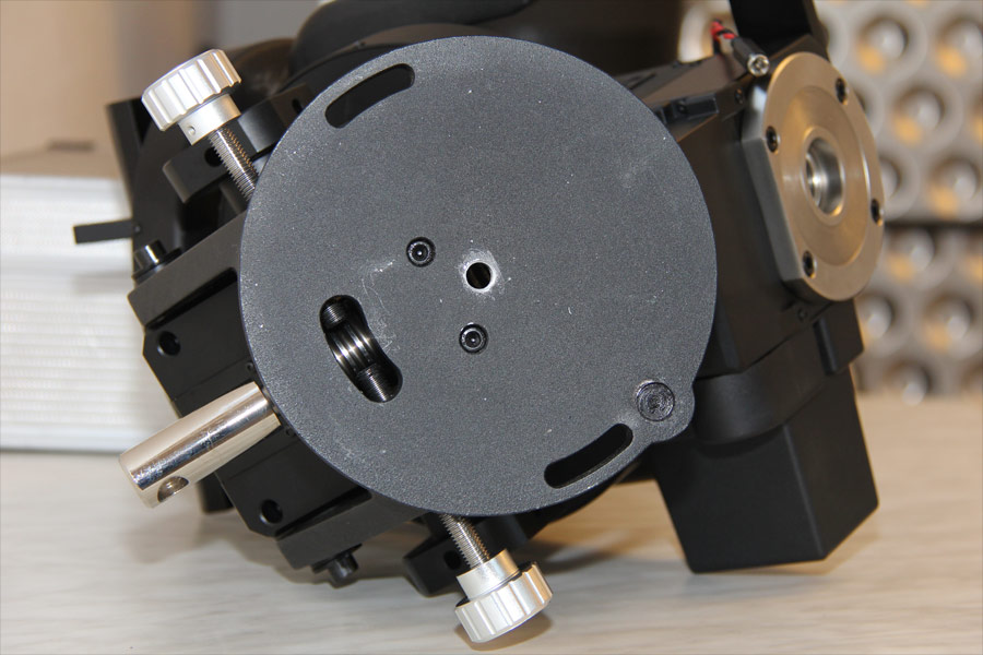
The base plate of the mount head with holes for three mountig screws and the pivot for azimuth adjustment. The azimuth adjustment is made with two rotary knobs and threaded bars which are pushing on the azimuth pivot from both sides. |
| |
| |
| |
Images from the tripod of the EQ8
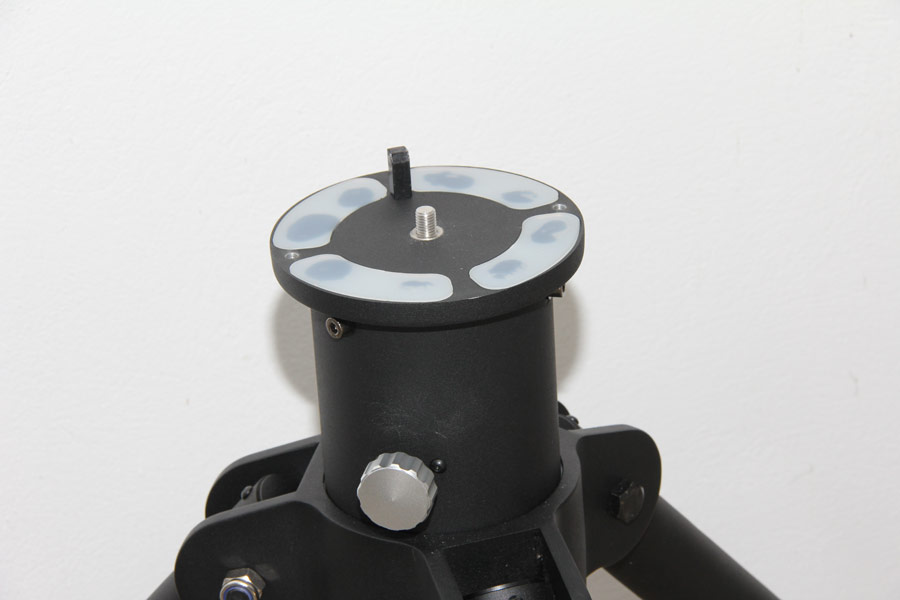
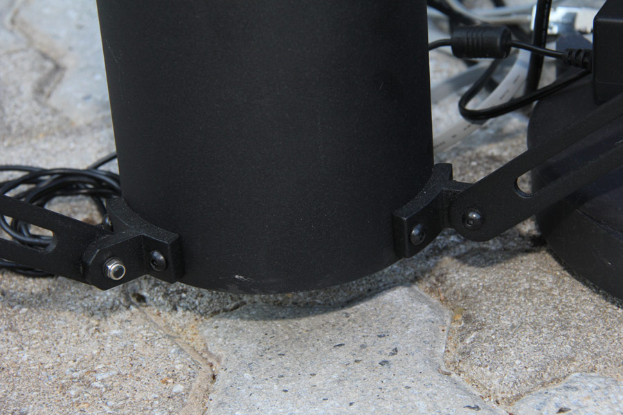
On the tripod top are some cut outs with glued Teflon pads to allow a movement of the screwd mount head with full load. After the azimuth alignment both screws on side ways will be tightened. |
| |
| |
| |
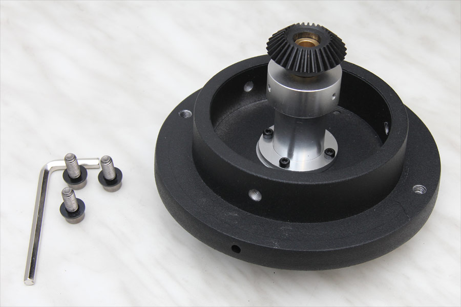
The unscrewed cover plate with the bevel gear wheel for the center screw. |
| |
| |
| |
The M12 center screw is reaching through the cover plate. But it is spring loaded and so can be pushed all the way down. Also the pivot for the azimuth adjustment is screwed in the cover plate with a M10 thread. |
| |
| |
| |
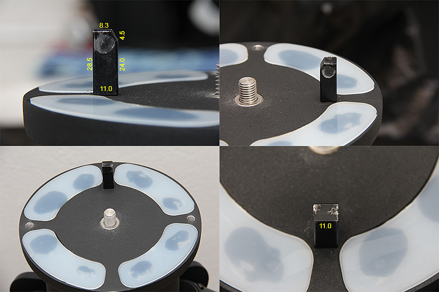
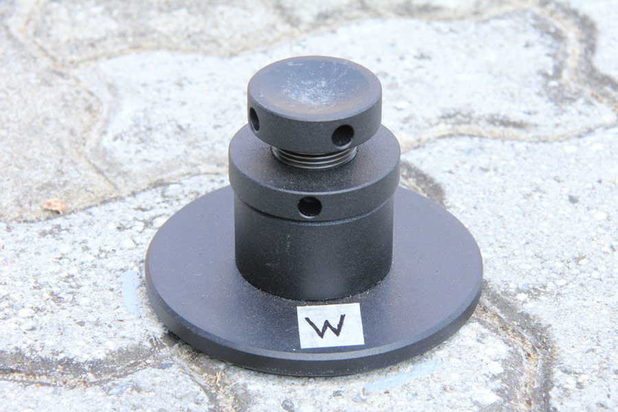
The pivot for the azimuth adjustment has the dimensions 11 x 11 x 28.5 mm. And it is beveled for some millimeters on the top. |
| |
| |
| |
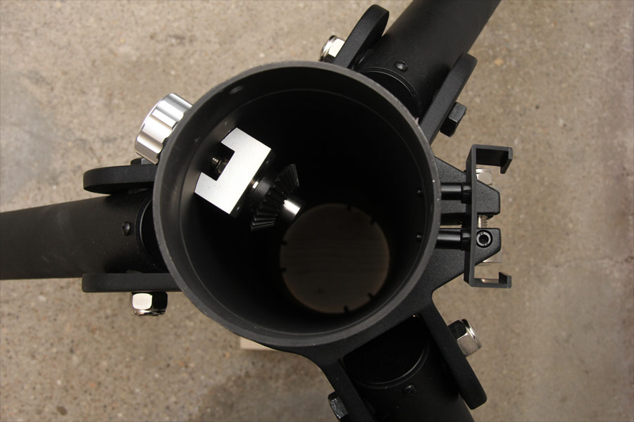
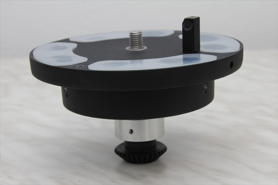
The second bevel gear wheel is mounted on top of the center tube of the tripod an can be rotated from outside with a rotary knob. Because of this the screw and unscrew of the mount head with the M12 screw is very easy. |
| |
| |
| |
The bearing bloc of the bevel gear axis in detail. |
| |
| |
| |

The rotary knob made from Alu is mounted with two screws on the axis. |
| |
| |
| |
The heavy tripod is made very solid and processed good. On the tripod a mount for the hand controller can be screwed. |
| |
| |
| |
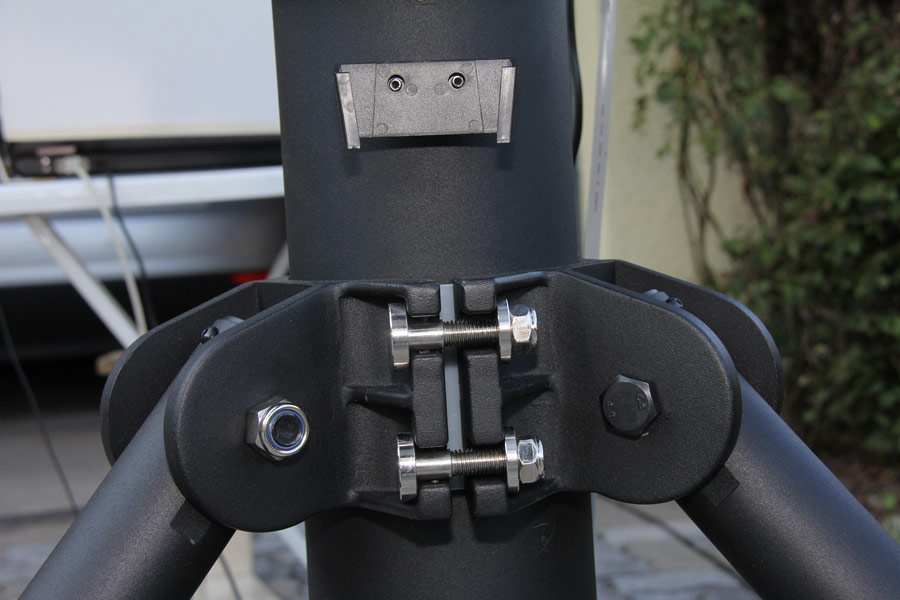
The height adjustment of the center tube on the tripod is done by moving the solid center tube. It will be clamped by two big screws. |
| |
| |
| |
The bearing of the tripod legs on the clamp of the center tube is made very solid. |
| |
| |
| |
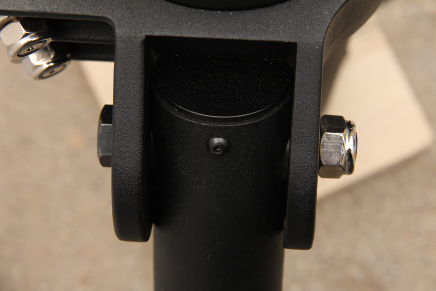
The bottom end of the center tube with the adjustable bars reaching to the tripod legs. |
| |
| |
| |
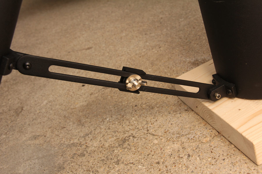
The length adjustable struts of the tripod legs. |
| |
| |
| |
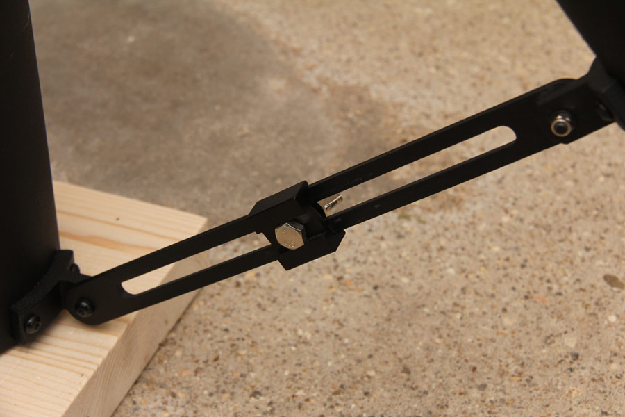
At the lowest level of the tripod the struts of the tripod legs are total extended. |
| |
| |
| |
The three level plates for the tripod legs can be adjusted in height to compensate level differences of the ground. An individual labeling and height adjustment shortens the setup time at a known location. |
| |
| |
| |
The rounded end of the tripod legs are standing save in the cavity of the height adjustable level plates. |
| |
| |
| |
Images from selfmade EQDirect adapter for mount EQ8
The EQ8 EQDirect adapter was also selfmade like the adapter on the EQ6. He is used to convert voltage levels in a serial data transmission in both directions. The logic levels at the new mounts and hand controller from Skywatcher are no longer TTL level with 5 volts but low voltage level with 3.3 volts. The level on the RS232 connection to the PC with a range from +/- 3 to +/- 12 volts of course has remained the same.
Important note: The motor controller elctronic in the EQ8 mount can also work with 5 Volt TTL levels as used in older hand controllers or EQDirect adapters for older Skywatcher mounts without any damage.
|
| |
| |
| |
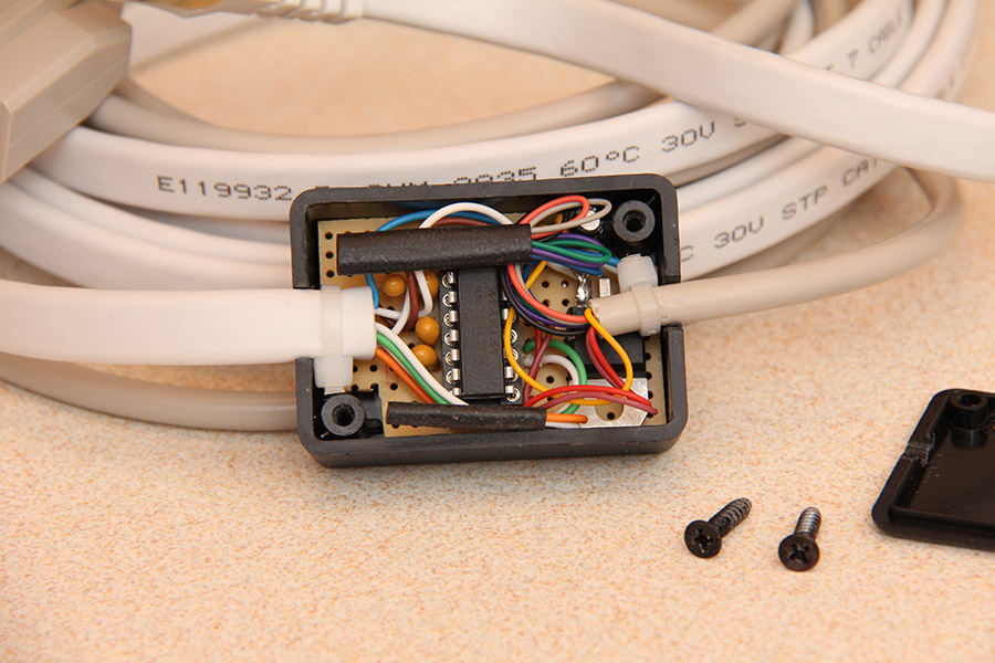
The circuit of the EQ8 EQDirect adapter has been assembled on a breadboard and placed in a 50x32x20mm black plastic box. |
| |
| |
| |
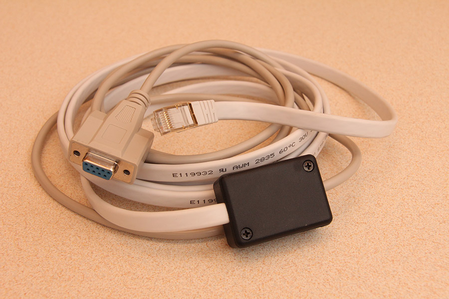
From the small box leads a RS232 cable to a 9-pin SUB-D female connector and a network cable to an 8-pin RJ-45 connector. |
| |
| |
| |
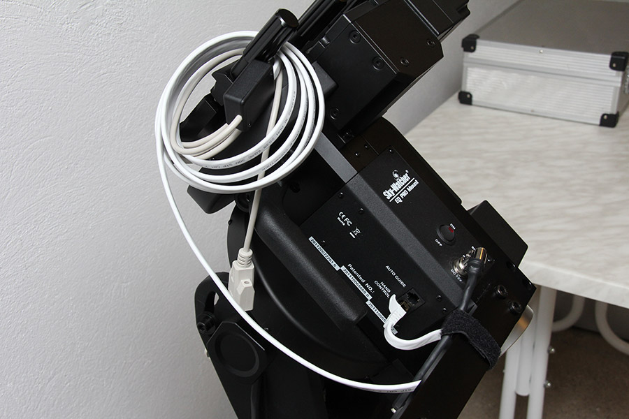
The adapter with cable remains permanently connected to the EQ8 mount and is transported with the mount head. |
| |
| |
| |
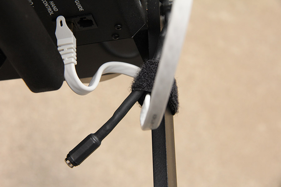
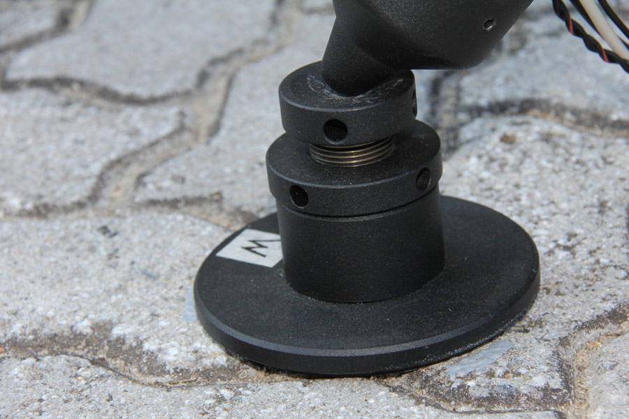
A hook-and-loop tape on the rail of the polar finder scope provides a stable support for the data connection to the PC and the 12V DC supply to the switching power supply. |
| |
| |
| |
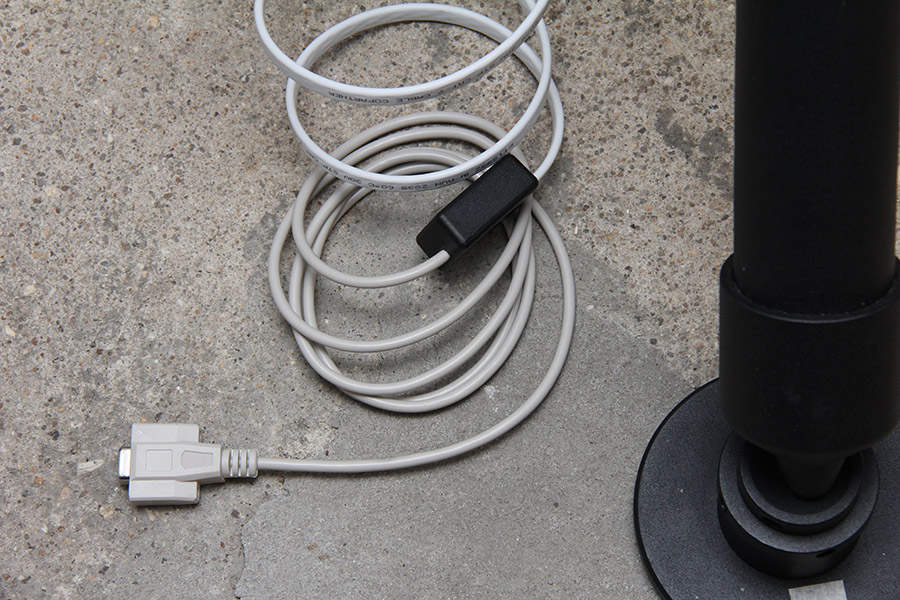
The 2.5 meter network cable is reaching relaxed the ground and the adapter box. And the serial cable with another 1.8 meters extends from the other end of the adapter box to the notebook on the table beside the mount. |
| |
| |
| |
EQ8 Mount - Pages overview
Page #1 - History, decision and purchase of the Skywatcher EQ8 mount
Page #2 - Mobile setup of the EQ8 mount with Newton telescope
Page #3 - Current draw and power supply of the EQ8 mount
Page #4 - Detailed images of the EQ8 mount (this page)